Frame
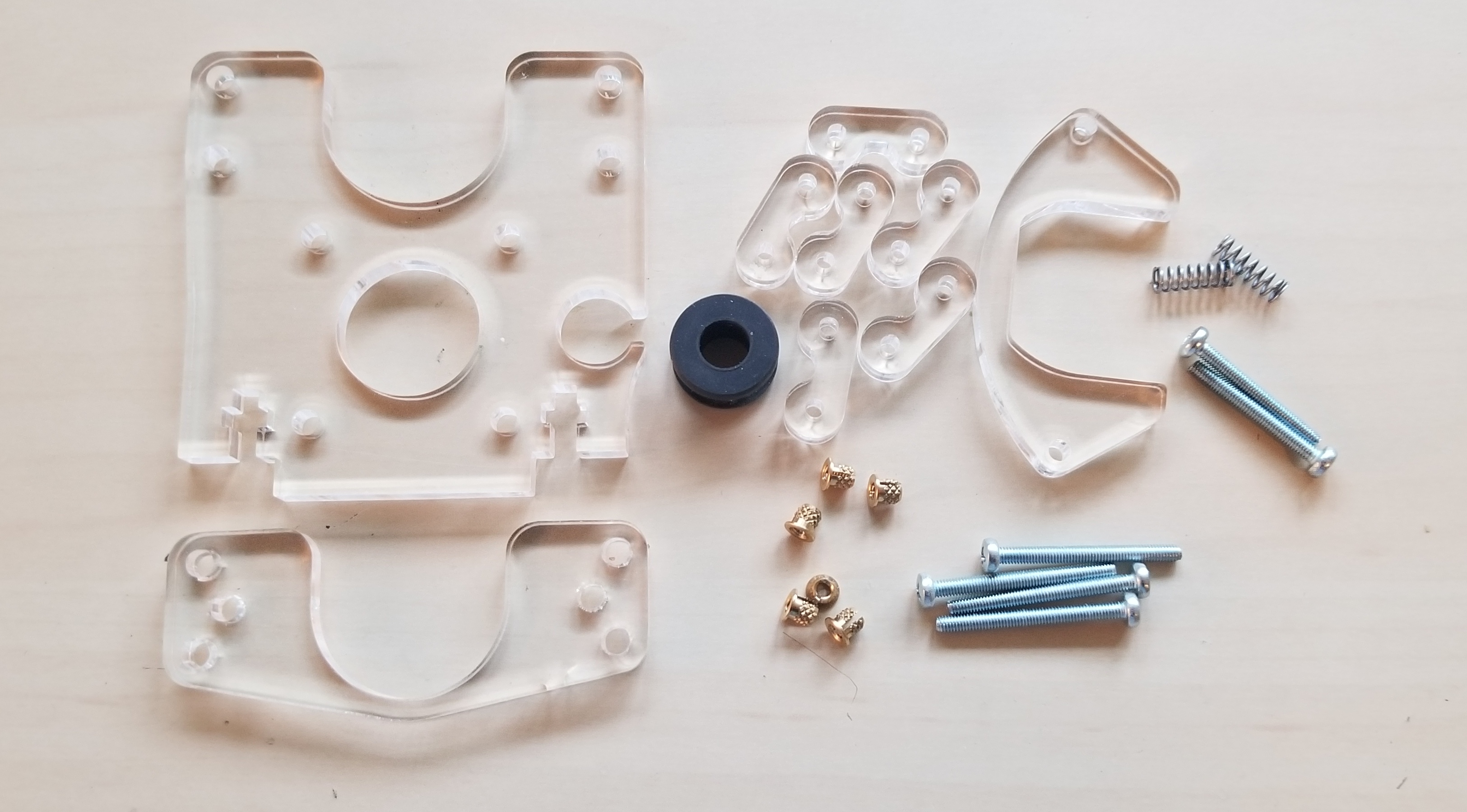
Design Files For Laser Cutting
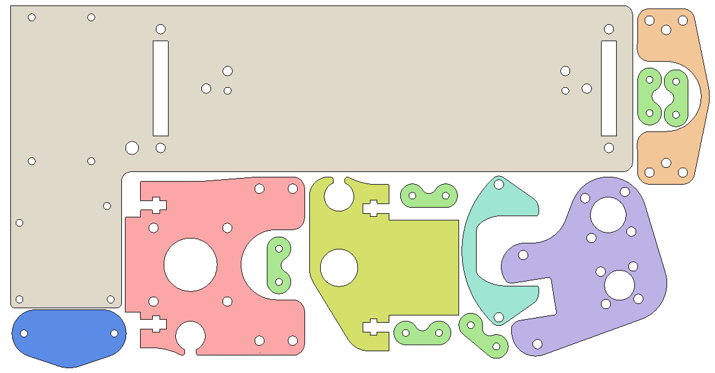
Note
If you don’t have access to a laser cutter, you can try searching for a local makerspace that has a laser cutter. Alternatively, you can order laser cut parts from a service like Ponoko or Sculpteo or Big Blue Saw
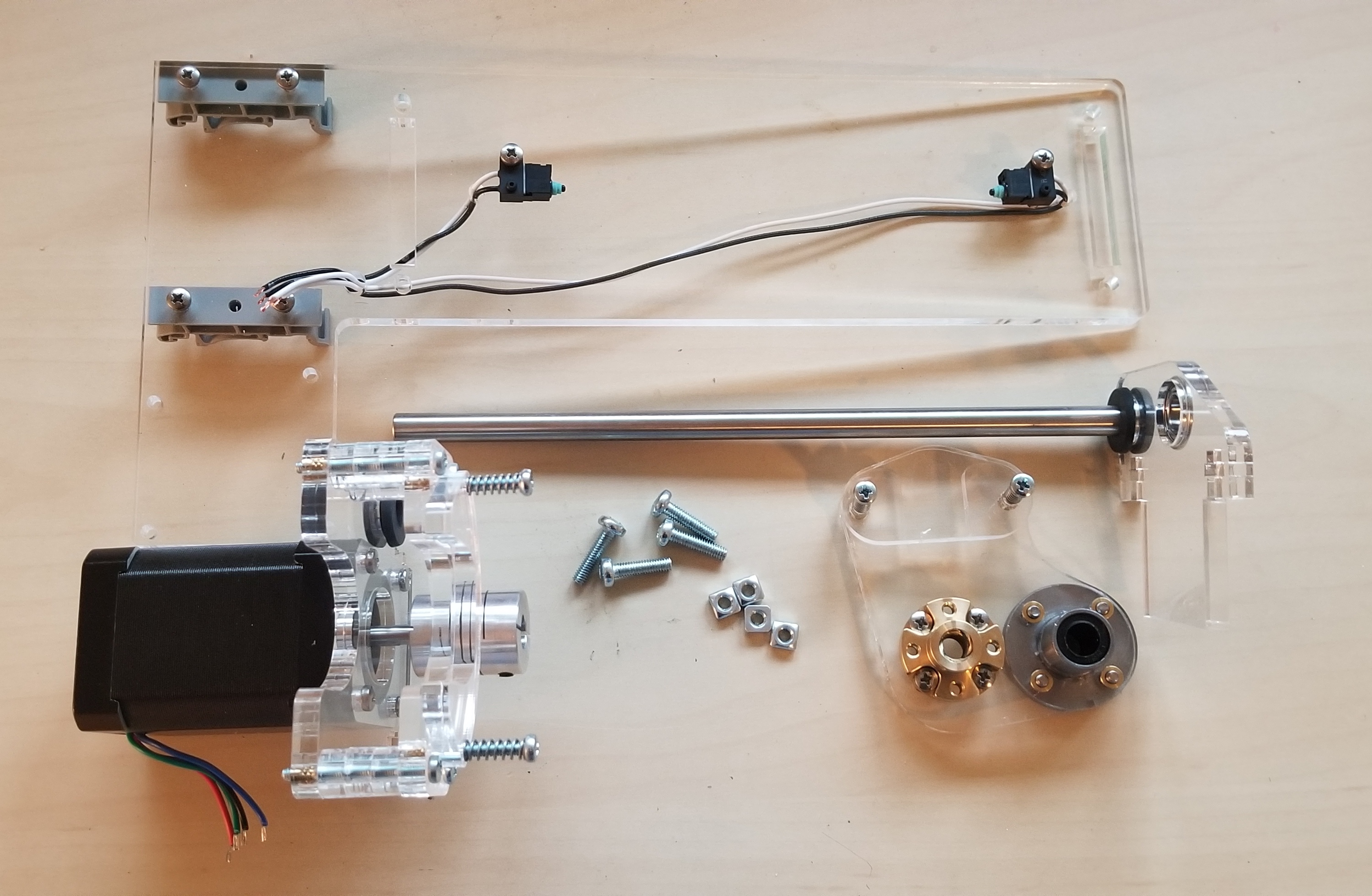
Bill of Materials
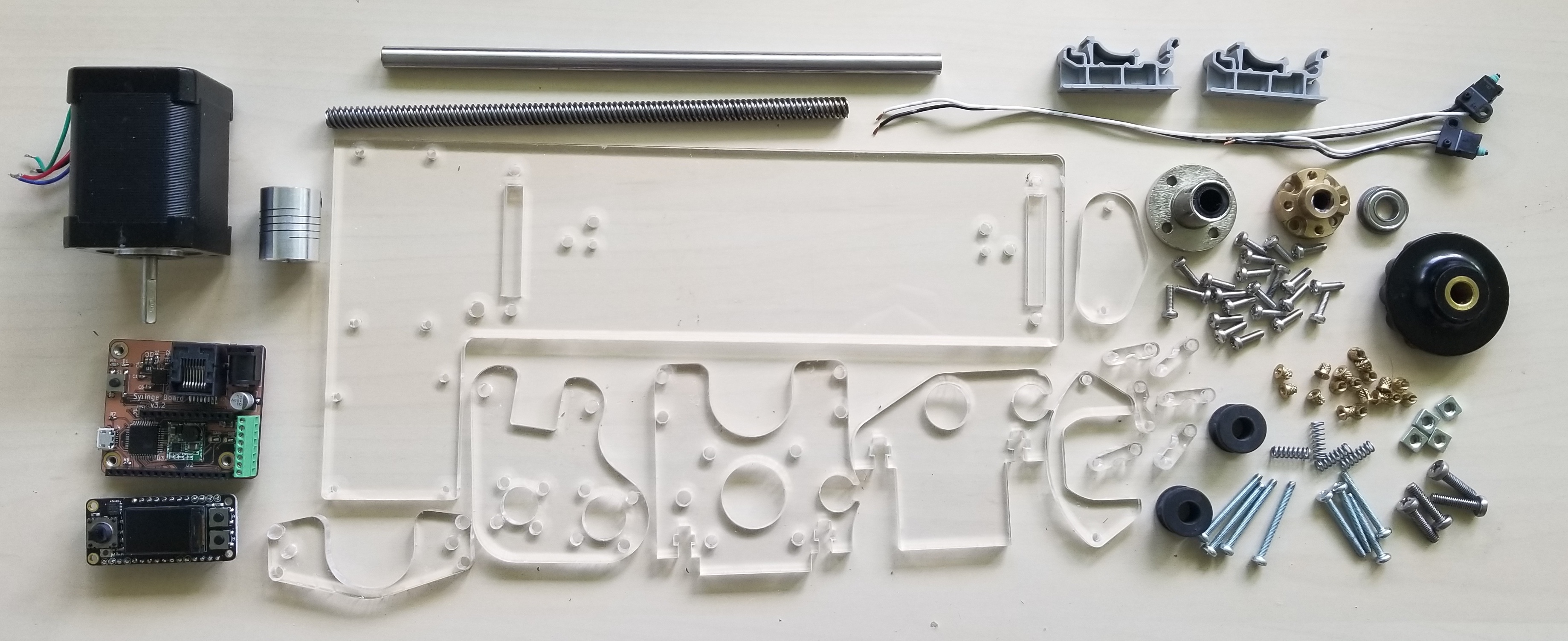
QTY |
Description |
Part Number |
Supplier |
|---|---|---|---|
1 |
12” x 12” x 1/4” Acrylic |
McMaster-Carr |
|
2 |
Grommet |
||
1 |
Flanged ball bearing |
||
4 |
M4 x 16mm machine screw |
||
4 |
M4 square nut |
||
4 |
M3 x 25mm machine screw |
||
4 |
M3 x 30mm machine screw |
||
22 |
M3 x 10mm machine screw |
||
18 |
M3 Threaded insert |
||
4 |
Spring |
||
1 |
Knob |
||
1 |
350 x 8mm lead screw |
ServoCity |
|
1 |
8mm lead screw nut |
||
1 |
200 x 8 mm shaft |
||
1 |
5 mm to 8 mm coupler |
Amazon |
|
1 |
Flanged LMF8UU slide bearing |
||
2 |
Limit Switch |
Digi-Key |
|
2 |
DIN clip |
||
1 |
Nema 17 bipolar 60Ncm 200steps |
STEPPERONLINE |
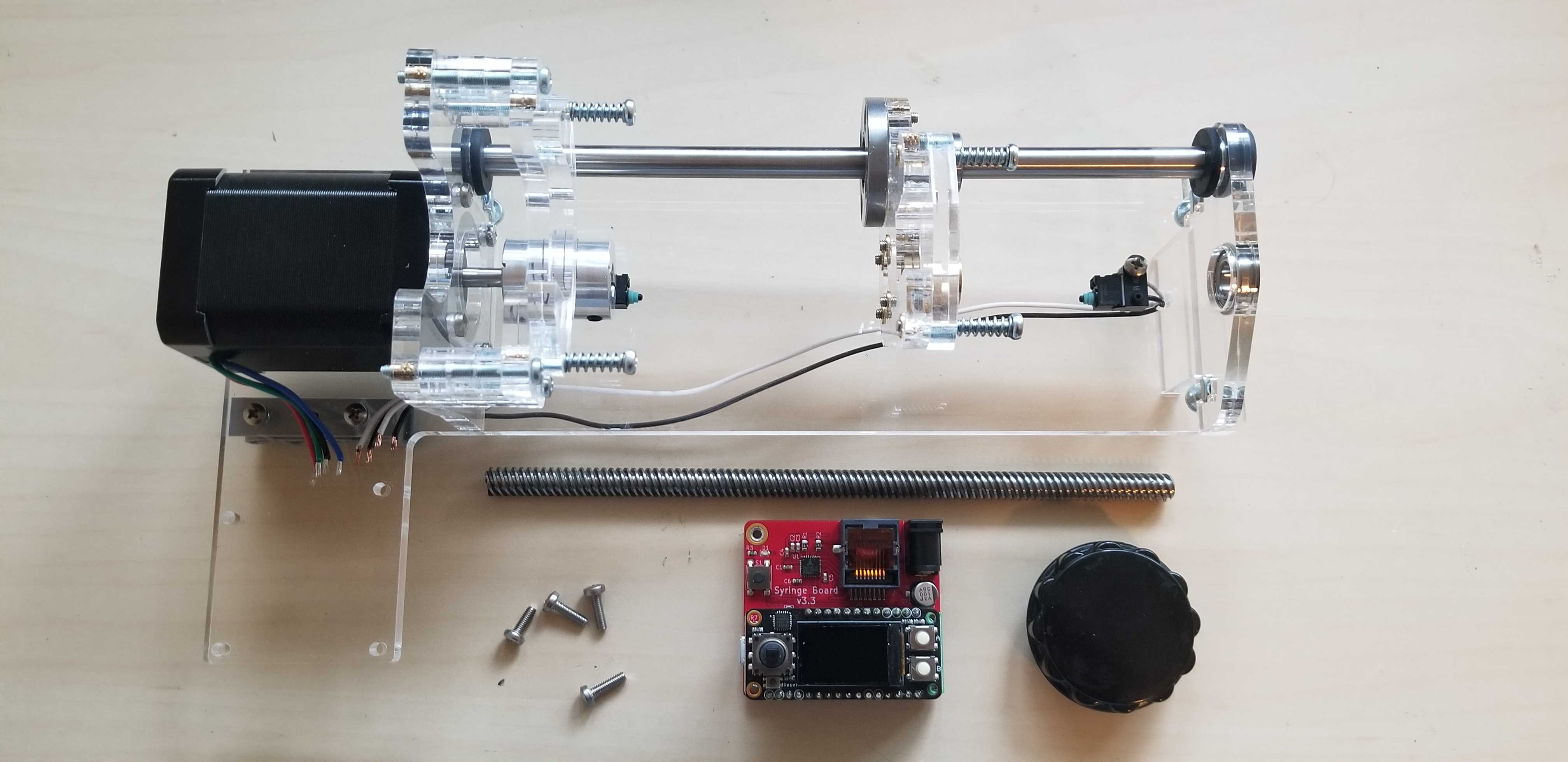
Assembly
Required Tools
Phillips screwdriver
Flathead screwdriver
Allen wrench (included with shaft coupler)
Wirecutters
Wire strippers
Instructions
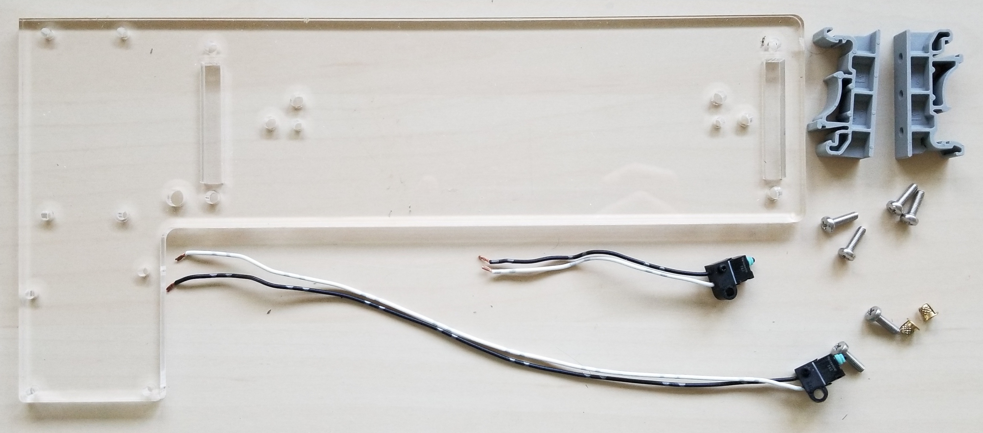
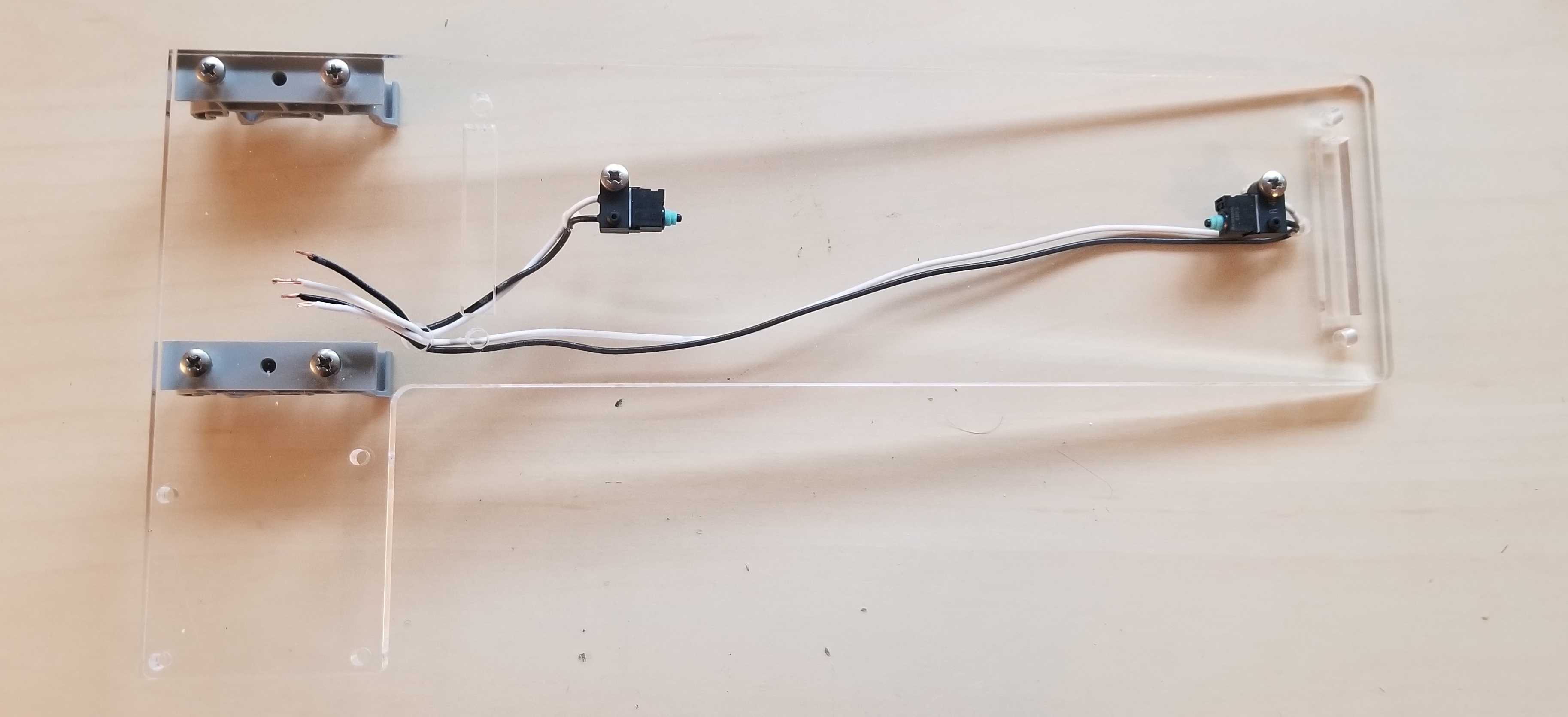
1. Assemble base
(6) M3 x 10mm screws
(2) M3 threaded inserts
(2) Limit switches
(2) DIN clips
Note
Cut the limit switch wires to 24cm and 9cm.
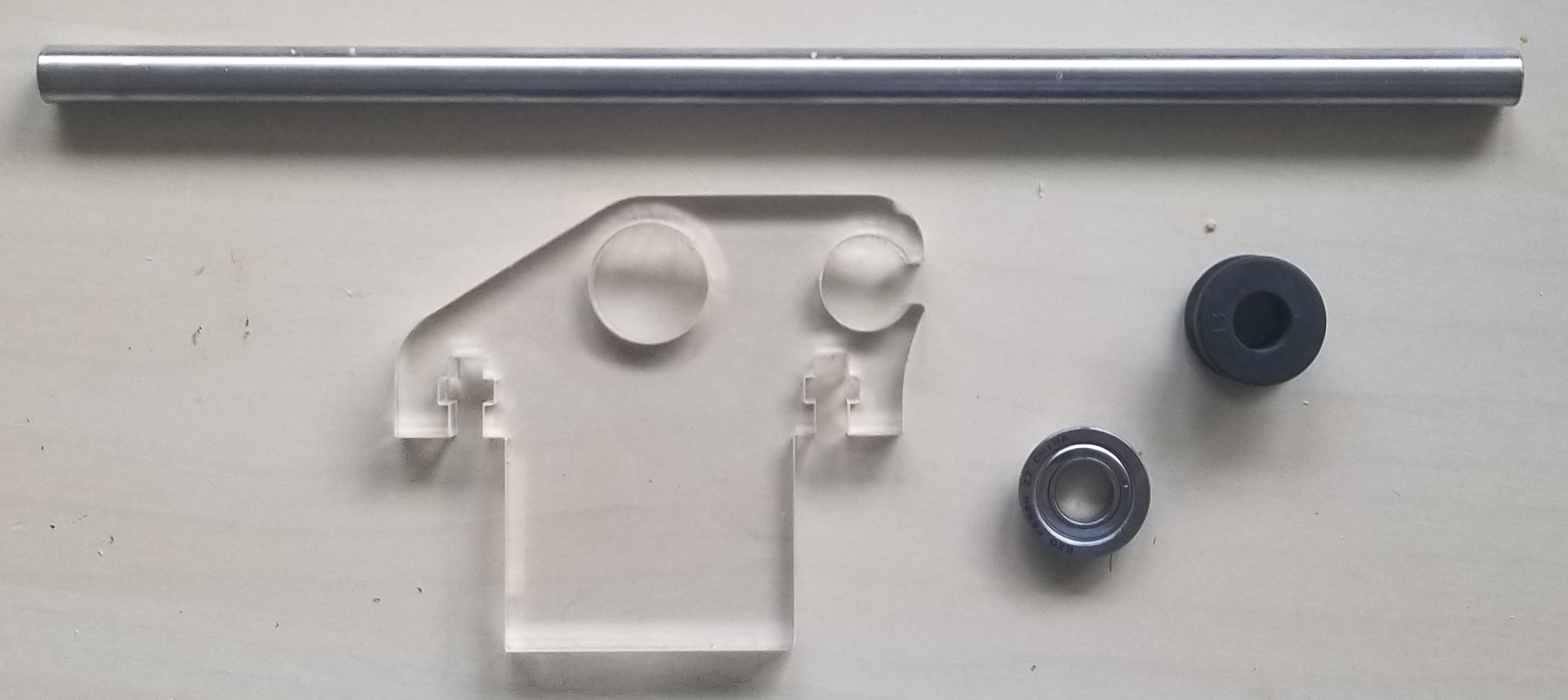
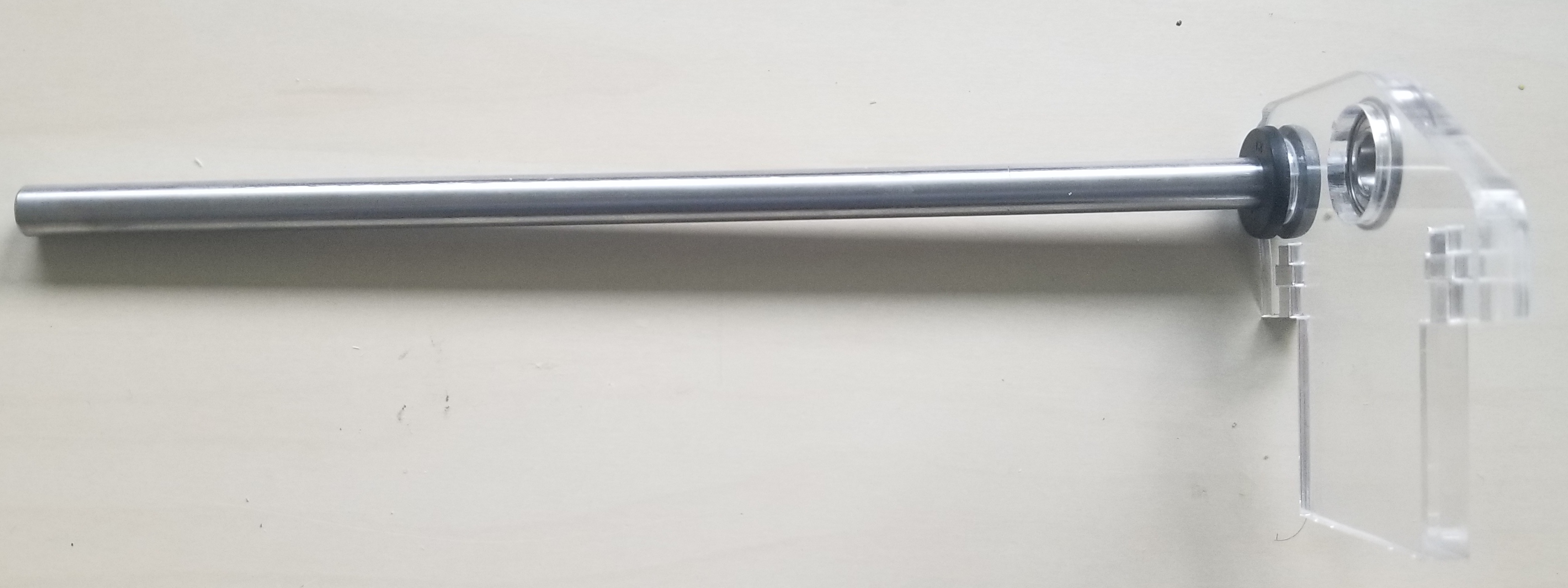
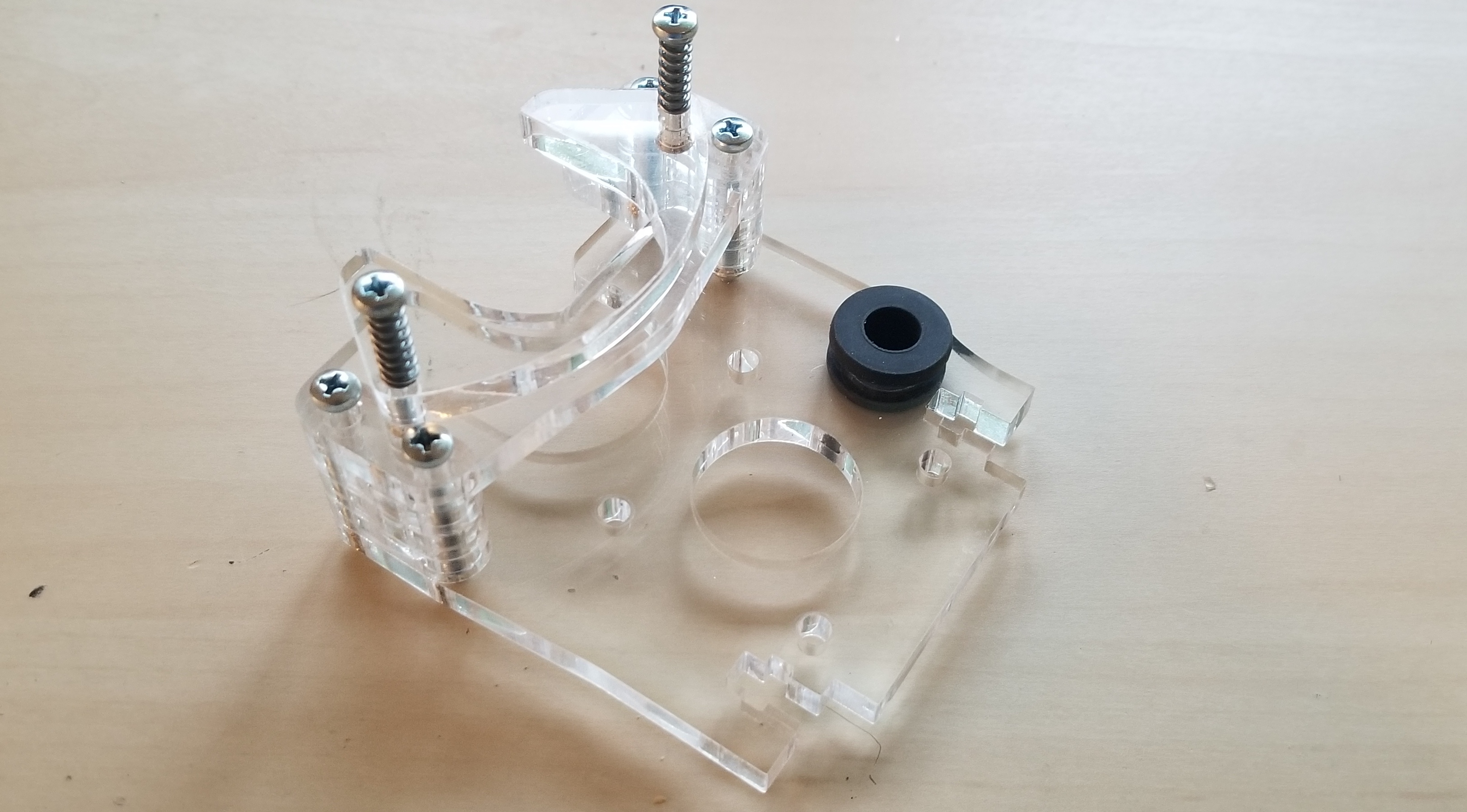
2. Assemble end support
(1) Flanged ball bearing
(1) Grommet
(1) 200 x 8 mm shaft
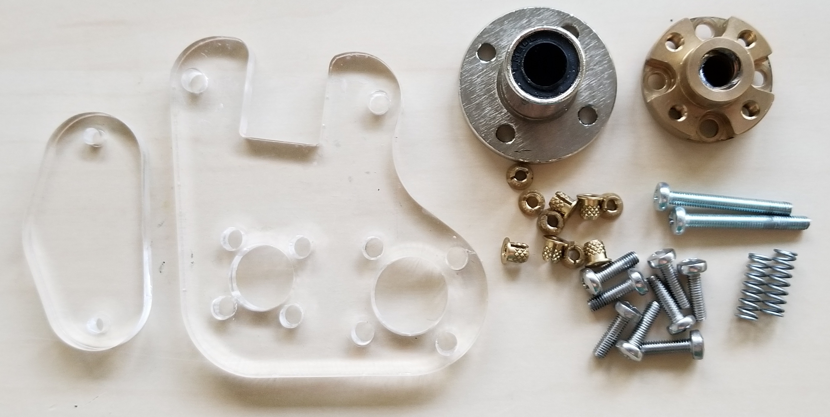
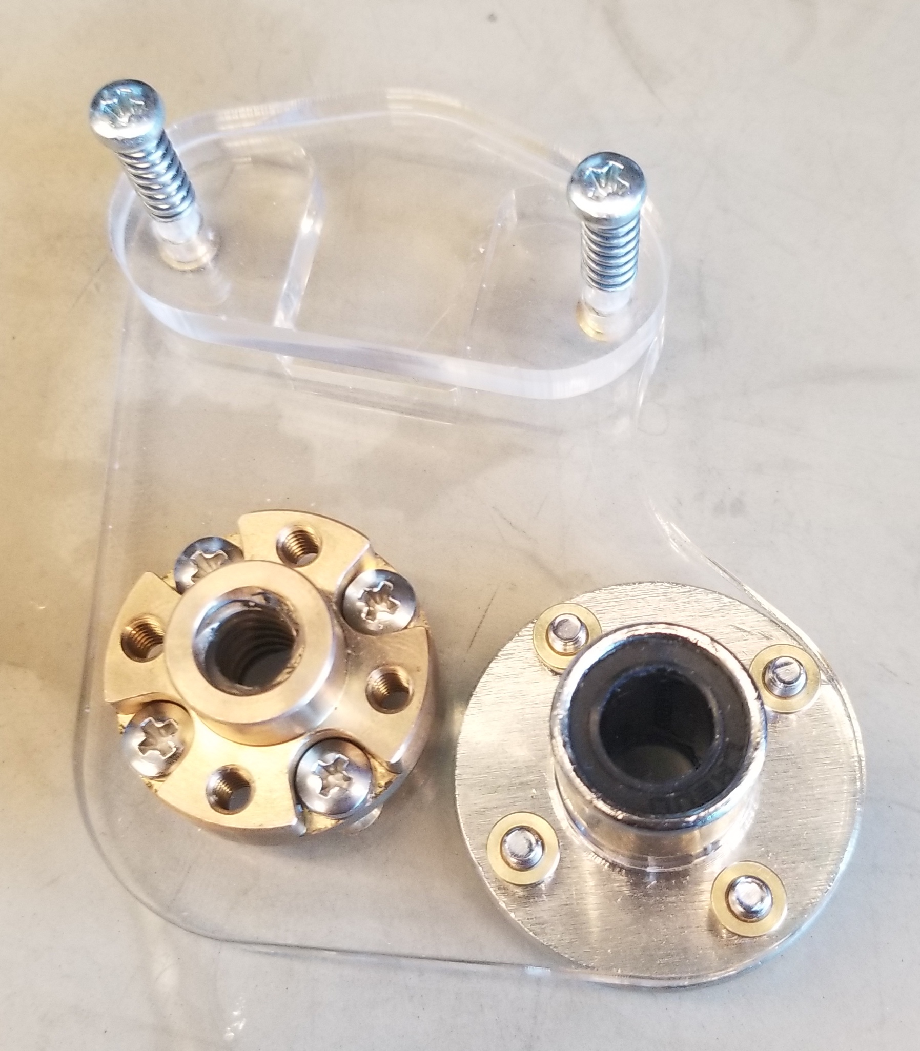
3. Assemble plunger carriage
(10) M3 threaded inserts
(8) M3 x 10mm screws
(2) M3 x 25mm screws
(1) Lead nut
(1) Linear bearing
(2) Springs
4. Assemble syringe cradle
(6) M3 threaded inserts
(4) M3 x 30mm screws
(2) M3 x 25mm screws
(2) Springs
(1) Grommet
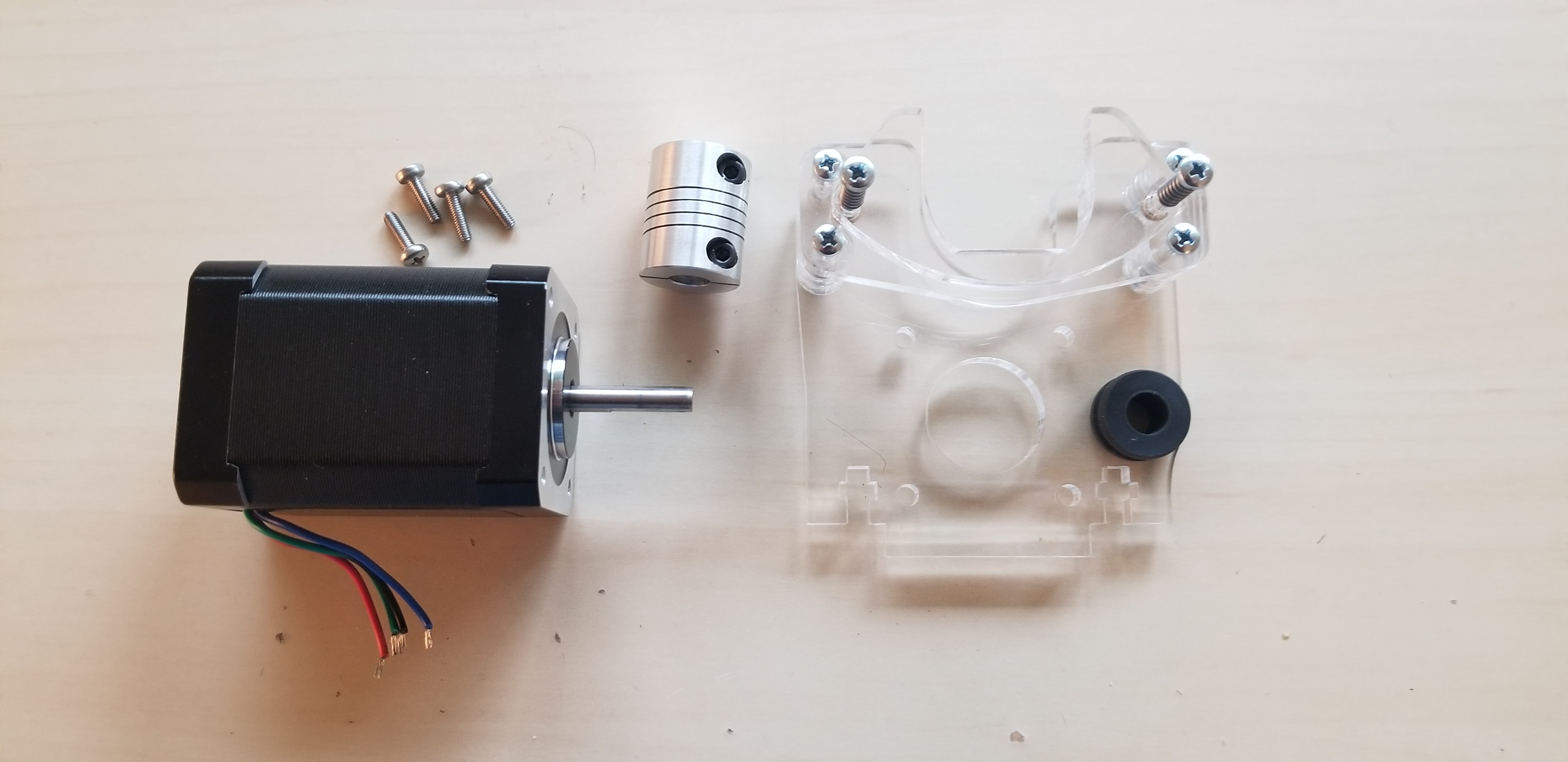
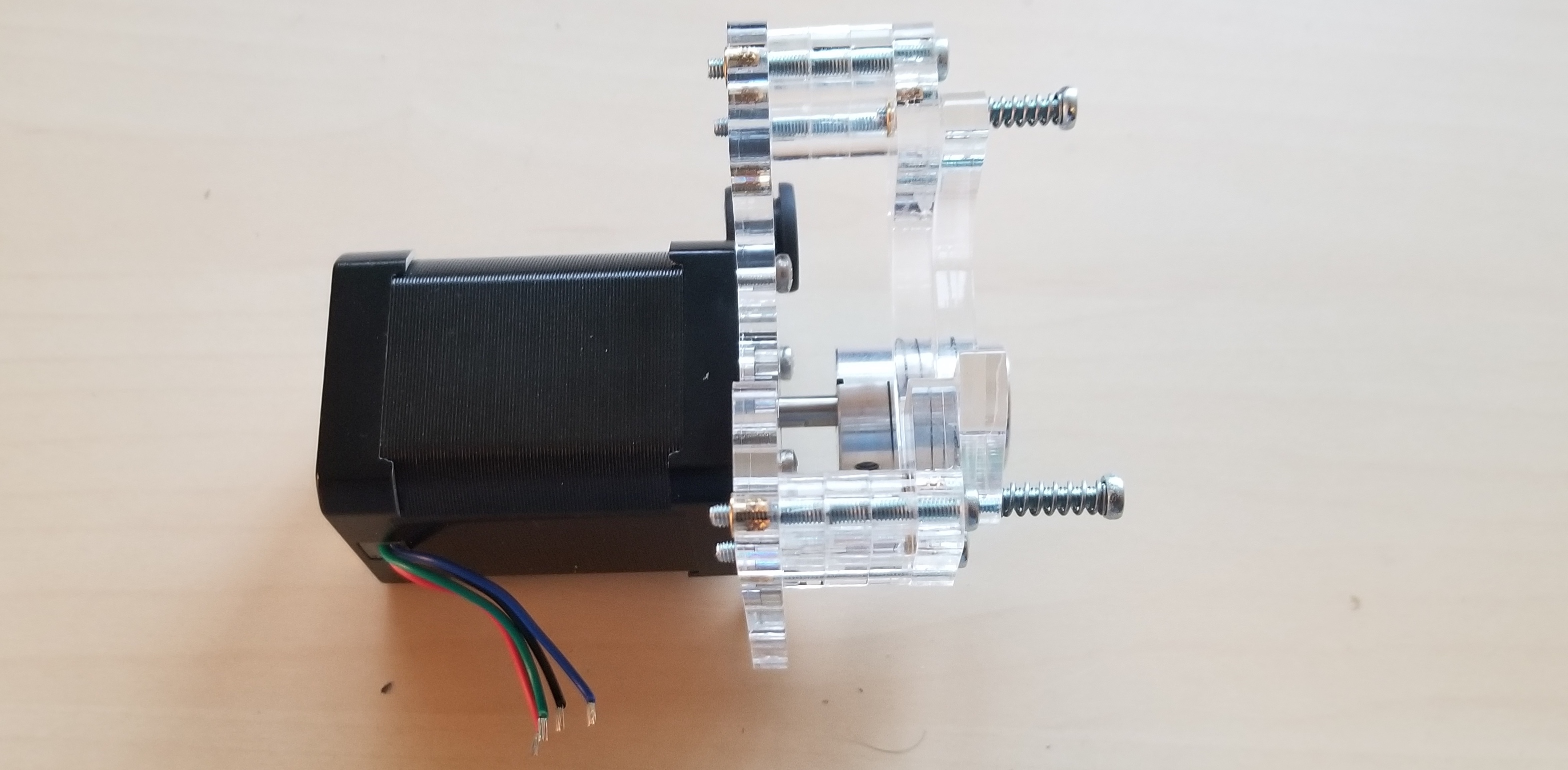
5. Mount motor to syringe cradle
(1) Stepper motor
(4) M3 x 10mm screws
(1) Coupler
(1) Syringe cradle
6. Combine sub-assemblies
(1) End support Assembly
(1) Motor Assembly
(1) Carriage Assembly
(4) M4 x 16mm screws
(4) M4 square nuts
Note
Cut the motor wires to 5cm.
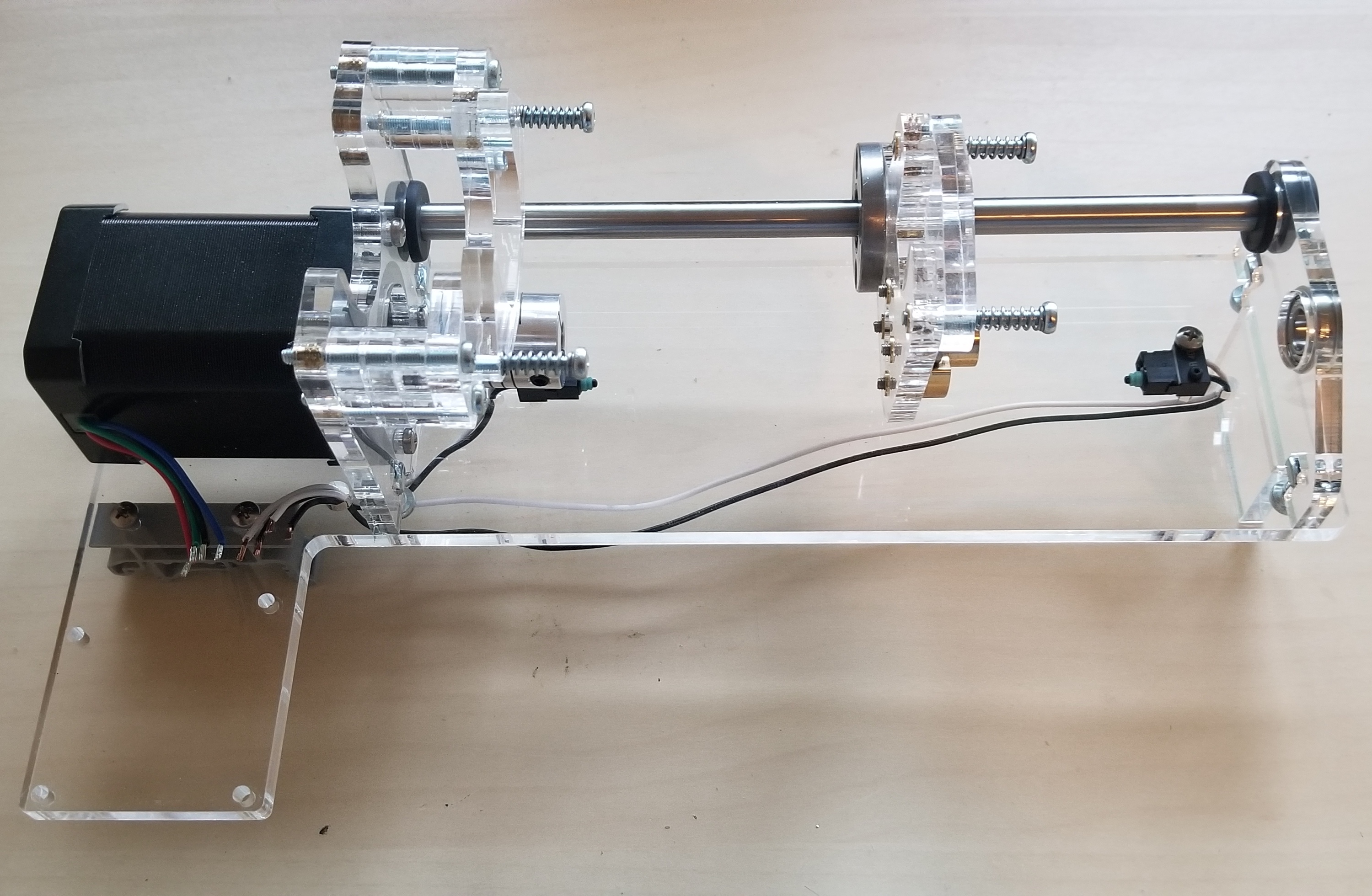
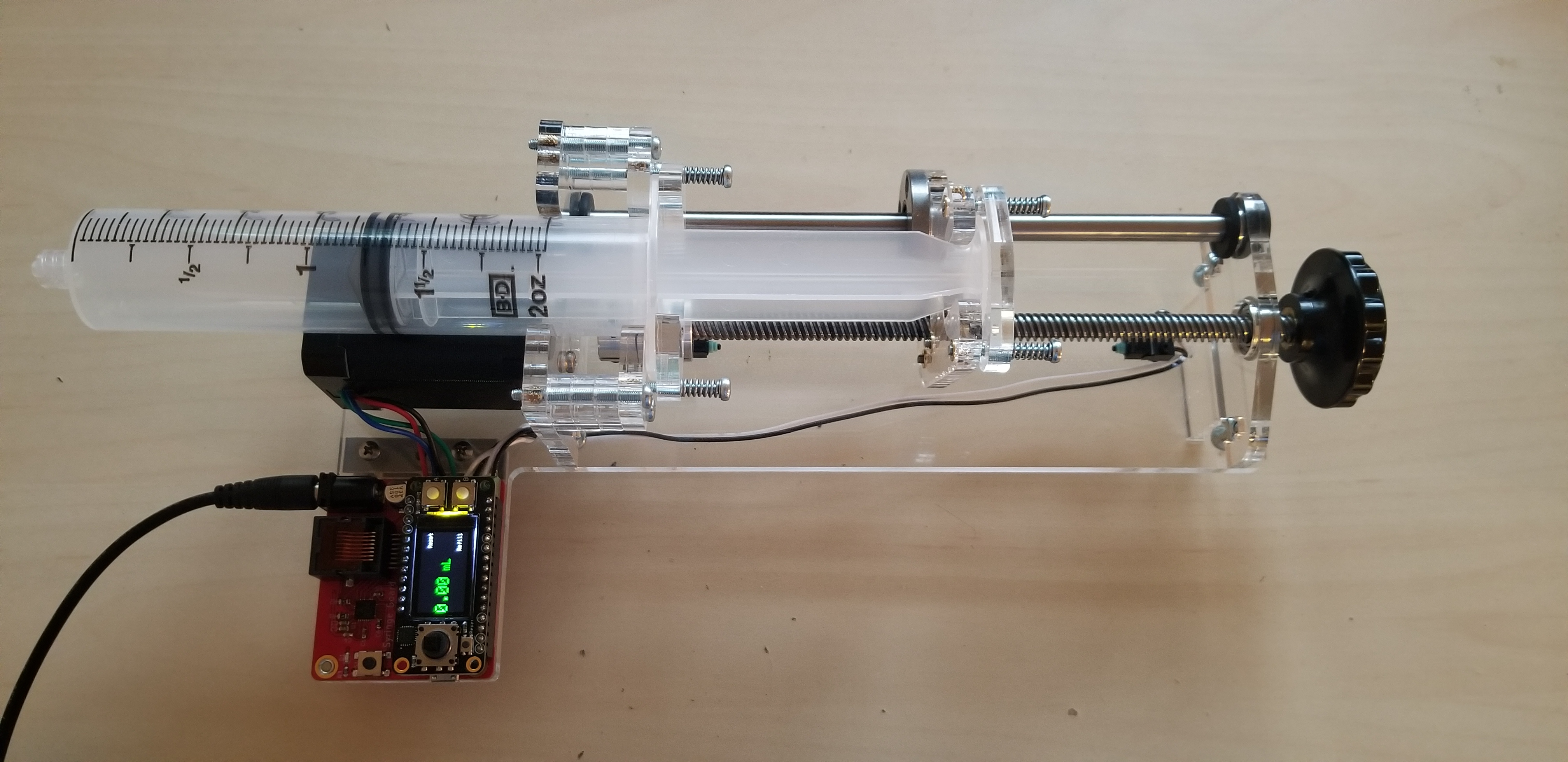
7. Install leadscrew, and connect Motor controller
(1) Lead screw
(1) Knob
(1) Motor Controller
(4) M3 x 10mm screws